

PEEK seal performance depends on more than the mechanical strength or temperature resistance of the polymer. For a high-pressure application, the critical questions are whether the PEEK component serves as a primary seal, backup ring or other functional element, how it interacts with the surrounding hardware, and whether the complete sealing assembly has been validated under the intended operating conditions.
PEEK (polyetheretherketone) material data provides a useful starting point. However, a material datasheet cannot independently establish a finished seal's allowable pressure, leakage performance or service life. Those outcomes depend on the selected grade, seal geometry, gland clearance, temperature, pressure history, operating medium and motion.
The following framework explains the selection sequence, what published PEEK data can establish and what evidence is required before approving a high-pressure application.
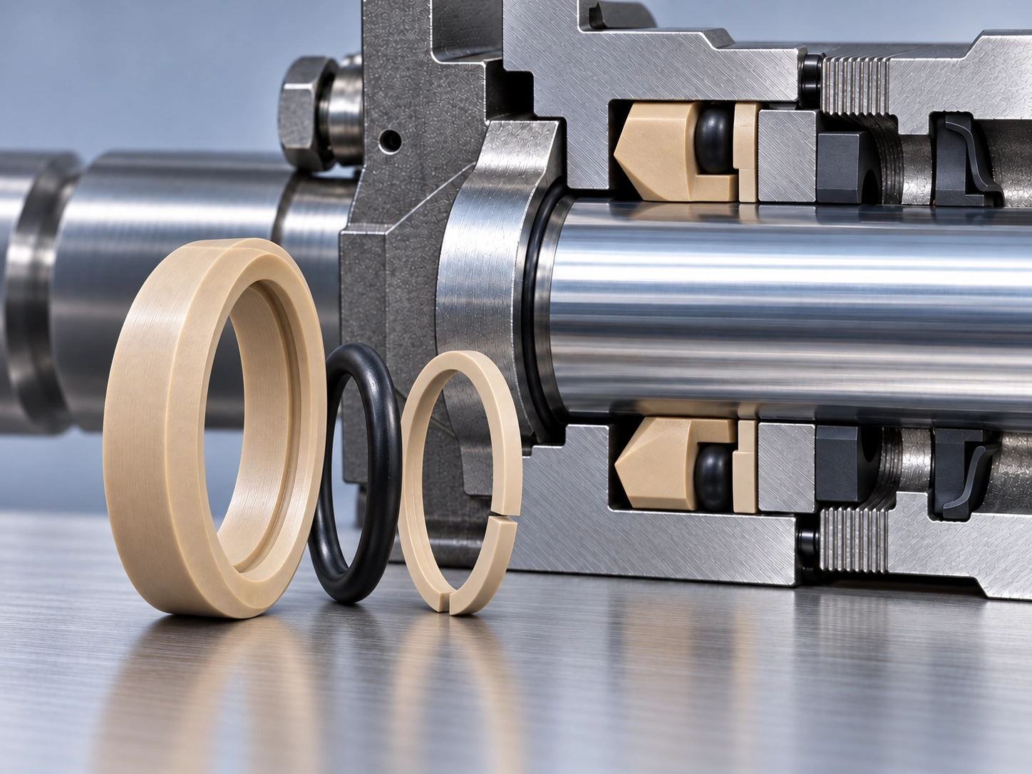
Identify the PEEK Component Before Assessing Performance
Primary seal or backup ring?
The first step is determining what the PEEK component is designed to do.
A primary seal forms the intended sealing interface that restricts fluid or gas leakage. A backup ring supports another sealing element, typically by limiting the deformation or extrusion of a softer seal into a clearance gap under pressure.
Other PEEK components may serve as guide rings, wear rings or mechanically supporting elements. These functions involve different contact conditions, dimensional requirements and acceptance criteria.
| Component function | Primary responsibility | Critical evaluation |
|---|---|---|
| Primary sealing element | Establish the intended leakage-control interface | Contact geometry, leakage, pressure, temperature, motion and wear |
| Backup ring | Support a primary seal against extrusion | Clearance gap, pressure direction, deformation, support geometry and compatibility |
| Guide or wear component | Support alignment or manage mechanical contact | Contact load, clearance, friction, wear and dimensional stability |
These categories are functional descriptions, not interchangeable product specifications.
Parker's Wedged Back-up Rings technical guide, identified as EPS 5256, 11/2014, describes a two-piece wedged backup arrangement used with elastomeric seals. Pressure acting on the primary seal loads the backup assembly, allowing its wedged elements to move and bridge the relevant extrusion clearance.
For this particular Parker WB design, the backup assembly supports the elastomeric sealing element rather than serving as the primary seal itself.
This does not mean every PEEK ring functions only as a backup. A separately engineered PEEK primary sealing component may perform a different role, but it requires performance evidence relevant to that specific design.
A drawing review should establish:
- Which component forms the intended sealing interface.
- Whether the PEEK part supports, guides or seals.
- The location and geometry of the gland.
- The adjacent sealing and mating materials.
- The direction or directions of applied pressure.
- The intended leakage path and acceptance requirements.
If a supplier provides successful test results for a PEEK backup ring, those results do not automatically justify replacing the primary sealing element with the same material.
Follow a defined selection sequence
Before comparing material grades or pressure ratings, establish the following order of decisions.
First, define the component's function. Determine whether it must create a seal, prevent extrusion or support mechanical guidance.
Second, document the operating conditions. Record normal and transient pressures, temperature history, fluid exposure, operating duration and motion.
Third, review the complete sealing arrangement. Identify the primary seal, backup support, gland geometry, mating surfaces and possible extrusion paths.
Fourth, screen candidate PEEK grades. Compare grade-specific mechanical, dimensional, thermal and tribological evidence with the actual application.
Finally, identify the required validation. Determine what must be demonstrated through finished-part inspection and complete-assembly testing before use can be approved.
This sequence prevents a common selection error: choosing a material from an attractive datasheet value before establishing the actual function and loading conditions of the part.
Separate Material Properties from System Pressure Limits
A PEEK material property and a sealing assembly's allowable working pressure describe different quantities.
Compressive strength, tensile strength and creep resistance are measured using defined material specimens and test procedures. They are important for screening candidate materials, but they do not directly establish how a finished seal will behave inside a gland.
The installed assembly introduces additional variables, including component shape, contact stress, manufacturing variation, extrusion clearance, mating-surface condition and interaction with other sealing elements.
Three levels of performance evidence
The following evidence hierarchy provides a practical basis for reviewing a supplier's technical claims.
| Evidence level | What to examine | What remains to be established |
|---|---|---|
| Material specimen | Exact grade, test method, loading mode, temperature and duration | Behavior of the finished component in its geometry |
| Finished component | Dimensions, manufacturing route, inspection results and relevant component tests | Interaction with the gland, mating surfaces and other seals |
| Complete assembly | Defined hardware, fluid, pressure–temperature history, motion and acceptance criteria | Applicability to production variation and conditions beyond the test |
A complete assembly test provides more directly relevant evidence for sealing performance than a material specimen test. However, even an assembly test supports only the conditions and acceptance criteria it actually covers.
When reviewing a supplier's high-pressure suitability claim, determine whether it comes from a material datasheet, a component-level assessment or a complete sealing assembly test.
If an assembly test supports the claim, its report should identify the seal configuration, material grade, relevant dimensions, test medium, pressure history, temperature, duration, measured leakage and inspection results.
A statement that the assembly passed is incomplete unless the report also defines what constituted a pass.
Why compressive strength is not a pressure rating
The Victrex PEEK Properties Guide, in the file identified as 09-2018, reports compressive strength testing under ISO 604 at temperatures up to 250°C for a selection of Victrex materials.
That temperature is part of the reported material testing range. It is not a universal operating-temperature limit for PEEK seals, nor does it establish that every listed grade was tested at 250°C.
Similarly, a compressive strength value expressed in MPa must not be treated as the maximum allowable fluid pressure of a sealing system.
The material specimen and installed seal experience different geometries, constraint conditions and loading mechanisms. The finished assembly may also be affected by extrusion clearance, thermal deformation, pressure cycling, leakage and long-term loading.
Separately published maximum pressure and maximum temperature values do not demonstrate that both can be sustained simultaneously.
The practical rule is to require an assembly-specific basis for any allowable pressure claim. If the evidence covers only material properties, the pressure capability of the complete sealing system remains unverified.

Check Clearance and Pressure Direction
Clearance geometry is central to the assessment of a high-pressure sealing assembly.
An extrusion gap is a clearance into which a sealing element may deform under the applied pressure. Its effect depends on the sealing material, pressure direction, gap geometry, component support and operating conditions.
A backup ring may reduce the risk of the primary seal extruding into this clearance, but the required backup design is application-specific.
Single-acting and double-acting arrangements
In Parker's documented WB arrangement, the backup support is located downstream of the applied pressure relative to the primary sealing element.
For double-acting service, Parker describes a configuration using two wedged backup sets, with one positioned downstream for each direction of pressure.
This illustrates why pressure direction matters. A configuration designed around pressure acting from one side cannot automatically be assumed suitable for pressure reversal.
The correct arrangement depends on the actual seal profile, gland and manufacturer's design instructions.
For a single-direction system, identify the pressure-loaded side of the primary seal and the clearance that needs protection.
For a reversing-pressure system, evaluate the support arrangement in both directions. Include the pressure transition, temporary unloading and potential movement of the sealing components.
The existence of backup support on both sides does not independently establish double-acting capability. The complete configuration must still be suitable for the operating conditions.
How to review extrusion clearance
Begin with the actual gland and mating-part drawings rather than a generic clearance value.
- Identify the surfaces forming the gap.
Determine whether the relevant clearance is between a piston and cylinder, a rod and housing or another pair of mating surfaces.
State whether dimensions are expressed as radial or diametral clearance.
For a concentric circular arrangement, radial clearance is half the difference between the bore and shaft diameters. However, misalignment or eccentricity changes the local clearance distribution, so a nominal concentric calculation may not represent the largest gap present in service.
- Review dimensional tolerance limits.
Collect the relevant bore, shaft, groove and sealing-component dimensions, together with their tolerances.
Determine credible combinations of dimensions that increase the local extrusion clearance or reduce support. Consider how component position, assembly fit and manufacturing variation affect these combinations.
- Consider operating-temperature effects.
Review the thermal expansion characteristics of the PEEK grade, the mating hardware and other relevant sealing materials.
A clearance evaluated at room temperature may change during heating or cooling because adjacent materials do not necessarily expand by equal amounts.
- Account for operating deformation.
Determine whether pressure-induced deformation, shaft movement, misalignment, side loading or wear could alter the local gap.
The significance of each factor depends on the assembly design. Do not combine physically incompatible worst-case conditions or ignore combinations that can occur together.
- Evaluate every relevant pressure state.
Record the potential extrusion path during normal loading, pressure transients, sustained holds and reversal.
If movement changes the gap or contact arrangement, include the relevant operating positions.
- Compare the evaluated conditions with supporting evidence.
Check whether the selected primary seal and backup arrangement have applicable design guidance or test evidence for the resulting geometry and operating conditions.
If the evidence does not cover the evaluated clearance, the design remains an open validation item.
No universal acceptable extrusion gap can be established from PEEK material strength alone.
A useful drawing-review record identifies the controlling dimensions, tolerance assumptions, thermal conditions, expected deformation and pressure direction for each clearance assessment.
Record the assessment using the following fields. This is a review template, not measured data or an allowable-clearance specification.
| Record field | Information to document |
|---|---|
| Assembly identity | Drawing revision, gland location and operating position |
| Bore and rod/piston dimensions | Nominal dimensions, units and whether clearance is radial or diametral |
| Tolerances | Dimensional limits and the physically compatible tolerance combination evaluated |
| Eccentricity and alignment | Assumed or measured offset, side loading and the basis for the local-gap assessment |
| Temperature | Component temperatures and grade-specific expansion assumptions |
| Pressure direction | Loading side, reversal state and extrusion path |
| Operating deformation | Pressure deformation, movement and wear considered |
| Evaluated maximum local clearance | Calculated or measured value, units, method and assessment conditions |
| Supporting evidence and review status | Applicable design guidance or test coverage, unresolved items and responsible reviewer |
Evaluate Grade, Temperature and Time Together
The term PEEK describes a polymer family, not a single grade with identical properties in every formulation.
Unfilled PEEK, glass-filled formulations and other reinforced or wear-oriented compounds may exhibit different stiffness, thermal expansion, ductility, friction and processing characteristics.
For sealing applications, grade selection must reflect the function of the PEEK component and the conditions it will experience.
Filled versus unfilled PEEK
| Selection factor | Unfilled PEEK | Filled or reinforced PEEK | Required engineering check |
|---|---|---|---|
| Stiffness | Grade-specific baseline behavior | Fillers may increase stiffness, depending on formulation | Compare relevant directional and temperature-dependent properties |
| Thermal expansion | Depends on grade and temperature | Fillers can substantially change expansion behavior | Evaluate fit against mating-part materials |
| Creep and deformation | Requires load-, temperature- and time-specific evidence | Reinforcement may alter deformation response | Obtain directly applicable creep or component data |
| Contact and wear | Depends on the contact system | Wear formulations may target particular friction and wear conditions | Examine counterface, lubrication and loading |
| Ductility and assembly | Depends on geometry and grade | Some reinforced materials may be less ductile | Assess installation strain and potential damage |
| Manufacturing | Material form and processing route matter | Filler type and content affect processing and finish requirements | Confirm geometry, route and inspection capability |
These comparisons describe selection considerations rather than a universal ranking.
For example, a formulation with greater stiffness may appear attractive for resisting deformation under load. However, stiffness alone does not establish acceptable long-term creep, reduced leakage or compatibility with adjacent components.
The same formulation may introduce different thermal expansion behavior, contact conditions or manufacturing requirements.
A material substitution should therefore be evaluated using the exact candidate grades and the requirements of the complete component and assembly.
What creep data can establish
Creep is time-dependent deformation under sustained loading. For a high-pressure sealing component, it matters because dimensional changes may alter the support geometry, clearance or contact conditions during service.
Victrex reports tensile creep testing for PEEK 450G at 23°C, under constant stresses from 20 to 60 MPa, over 1,000 hours, using ISO 899.
These results are useful for understanding the tested material's response to sustained tensile loading under the stated conditions.
They do not establish elevated-temperature compression creep, finished backup-ring deformation or sealing-system life.
The loading mode matters. A test specimen subjected to uniaxial tension does not experience the same stress distribution as a constrained ring inside an assembled gland.
Temperature and time are equally important. A short-duration mechanical test does not replace evidence for repeated pressure holds or sustained exposure at operating temperature.
Before accepting creep data for a candidate part, review the following comparisons:
| Review question | Required comparison |
|---|---|
| Is the material the same? | Exact grade, formulation and relevant material form |
| Is the loading relevant? | Tension, compression or another loading mode |
| Is the temperature representative? | Test temperature against the application's thermal history |
| Is the duration sufficient? | Test duration against hold periods and intended service |
| Is the result usable? | Measured deformation against the component's acceptance criteria |
Where elevated-temperature compression or long-duration component data are missing, identify the gap explicitly.
The next step may involve obtaining additional supplier data, performing relevant component testing or conducting assembly-level validation. It should not involve assigning an allowable deformation or service life without an appropriate basis.
Evaluate combined thermal and pressure conditions
An application may expose a PEEK component to several operating states rather than a single constant temperature.
The evaluation should consider start-up, normal operation, temperature excursions, shutdown and any sustained periods at elevated temperature.
For each significant state, identify the pressure applied, duration of exposure, component temperature and expected geometric changes.
Where the application combines pressure cycling with temperature changes, assess whether the available evidence covers the combined loading history.
The selected material must also be assessed for the intended fluid or gas environment. Chemical compatibility must include the relevant operating medium, additives, concentration where applicable, temperature and exposure duration.
Evidence for the PEEK grade does not establish compatibility of the primary seal or other materials in the assembly.
Review Motion and Manufacturing Risks
Static and dynamic applications impose different requirements on sealing components.
A material that provides suitable dimensional support during stationary pressure holds may still require additional evidence when exposed to sliding contact, cyclic loading or changing lubrication conditions.
Conversely, PEEK should not be excluded from all dynamic sealing applications based solely on its material family.
Application-specific PEEK grades
Victrex's Seal Ring Solutions literature, carrying a 2019 copyright notice, describes PEEK grades developed for automotive transmission seal-ring applications.
The supplier identifies pressure, velocity and temperature as relevant selection dimensions, alongside grade-dependent stiffness, friction and dimensional behavior.
This establishes that PEEK formulations are used in specific engineered dynamic sealing applications.
It does not prove that the same formulations are suitable for an unrelated reciprocating hydraulic cylinder, valve gland or other high-pressure assembly.
Current grade availability and current technical specifications should be confirmed before material selection.
Static, reciprocating and rotary conditions
| Operating condition | Main evaluation focus | Useful validation evidence |
|---|---|---|
| Static sealing | Sustained pressure, temperature exposure, extrusion support and dimensional change | Pressure-hold leakage, dimensional inspection and post-exposure condition |
| Reciprocating motion | Repeated sliding, stroke length, reversal, friction, wear and lubrication | Leakage during cycling, wear inspection and friction measurements |
| Rotary motion | Speed, contact load, lubrication, temperature rise and mating-surface condition | Relevant pressure–velocity–temperature testing, friction, wear and leakage |
For a dynamic assembly, record the movement type, speed range, duty cycle, lubrication condition, mating-surface material and surface-finish requirements.
Where pressure and movement vary during operation, validation should represent relevant combined states rather than examining maximum pressure and maximum speed only as independent conditions.
The acceptance criteria should also cover the behavior of the complete sealing assembly, not just the wear resistance of the PEEK component.
Manufacturing route and finished-part quality
The manufacturing route affects the characteristics and consistency of the finished component.
For an engineered PEEK sealing part, the production plan may involve material compounding, stock-shape production, near-net-shape forming, machining or other secondary operations.
These are distinct manufacturing stages and should not be treated as interchangeable.
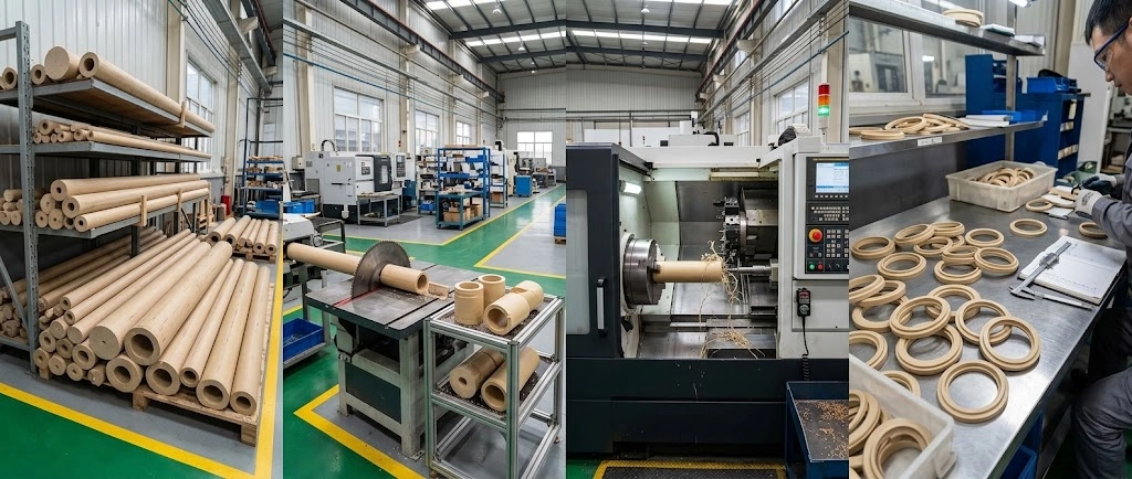
Material identification and preparation
Define the resin manufacturer, exact grade, filler formulation where relevant, material form and the required traceability.
If a supplier proposes a different grade, establish the technical basis for the change before accepting it.
Stock-shape or near-net-shape production
Material may be supplied as a rod, tube, plate or other stock shape for subsequent machining, or formed closer to its final geometry through a suitable process.
Extrusion, injection molding and other production routes serve different geometric and volume requirements.
An extruded rod or tube may become a machining blank; a continuous profile is not automatically a finished sealing ring. Injection-molded rings and other near-net-shape parts require their own grade, tooling, process and inspection assessment. Qualification of one production route does not establish qualification of another.
Machining and finishing
A finished sealing ring may require controlled bore and outside diameters, groove features, edges, split geometry and contact surfaces.
The drawing should specify which dimensions and surfaces are critical to assembly fit and performance.
Machining methods, tool condition, material stress and the selected blank can all influence the finished part. Their significance should be assessed against the actual component requirements.
Dimensional and visual inspection
Inspection requirements should be linked to defined drawing characteristics rather than an unspecified claim of precision.
Depending on the design, relevant checks may include dimensions, roundness, flatness, cut geometry, edge condition, visible defects and surface condition.
The selected inspection method must be capable of evaluating the specified characteristic.
Assembly validation
Passing dimensional inspection confirms only that the measured part characteristics meet the defined inspection requirements.
It does not independently prove sealing performance after installation.
The finished component must still be assessed with the primary seal, gland, mating hardware and intended operating conditions.
Split-ring inspection
Split-ring geometry deserves particular attention because the cut can influence installation, mechanical contact and local deformation.
In an article published on April 11, 2023, Port Plastics describes a potential failure mechanism involving scarf-cut backup rings.
The supplier explains that excessive material stress may cause the scarf-cut ends to overlap. With temperature changes and expansion of the adjacent O-ring, a sharp end may contact and damage the primary seal.
This is a supplier-described potential failure mechanism, not a demonstrated failure rate for all split PEEK rings.
For a proposed split-ring component, examine cut alignment, edge condition, residual deformation and the risk of contact with the primary sealing element.
Determine whether the application-specific inspection and test plan should examine these features after thermal exposure, pressure loading and assembly.
The relevant question is not simply whether the ring is made from PEEK, but whether its finished geometry and condition remain suitable for the intended sealing arrangement.
Build an Application Validation Checklist
Material selection, component inspection and sealing-system validation should produce separate, traceable decisions.
Before testing, the responsible engineering team should define the application conditions, test sequence, acceptance limits and evidence required for approval.
The following checklist provides a framework for preparing that review.
| Validation item | Information to agree before testing |
|---|---|
| Component identity | Function, drawing revision, exact grade, batch and manufacturing route |
| Assembly geometry | Gland, mating parts, tolerances, clearance definitions, assessment conditions and pressure directions |
| Operating medium | Fluid or gas composition, additives and exposure conditions; compatibility evidence for the exact PEEK grade, primary seal and other relevant contact materials |
| Pressure history | Normal operation, transients, hold periods, reversal and depressurization |
| Thermal history | Temperatures, ramps, dwell periods and pressure–temperature combinations |
| Motion | Static, reciprocating or rotary service; speed, duty cycle and lubrication |
| Acceptance criteria | Leakage measurement method and limit, dimensional change, wear and visible damage |
| Test coverage | Sample quantity and its basis, duration, cycles, inspection stages and reporting requirements |
| Open evidence items | Missing or mismatched data, their implications and the work needed to resolve them |
| Approval scope | Conditions supported by the results and changes requiring further review |
Recording an operating medium does not establish chemical compatibility. Compatibility evidence should cover the actual material grades and relevant exposure conditions.
Similarly, specifying a test pressure or cycle count is only part of the validation plan. The test must also define the expected result, measurement method and criteria for acceptance.
Organize validation into separate decisions
A practical validation sequence distinguishes four stages.
Stage 1 - Material evidence review
Confirm the candidate grade, relevant datasheets, test conditions and known evidence gaps.
If the published information does not cover the intended application, identify additional evidence needed before proceeding.
Stage 2 - Finished-component inspection
Inspect the manufactured component against its drawing and agreed acceptance criteria.
Record dimensions, visible defects, material identity and other required characteristics. Nonconforming parts should not be treated as approved merely because the material grade is correct.
Stage 3 - Complete-assembly testing
Test the actual sealing configuration under a defined sequence representing the intended operating conditions.
As applicable, include pressure holds, pressure reversal, temperature exposure, relevant motion and leakage measurements.
Record the test configuration, sample identification, conditions, observations and results.
Stage 4 - Review and approval
Compare the results with the acceptance criteria established before testing.
If a sample fails, a critical condition is not covered or the test configuration does not match the intended application, investigate the discrepancy and determine whether redesign or additional validation is necessary.
A passed material inspection does not constitute assembly approval. Likewise, an assembly test does not automatically validate future changes to the material, geometry or operating conditions.
The resulting approval should identify the component and the conditions it supports.
Use the evidence review to record a decision status rather than treating material selection as application approval.
| Decision status | Basis | Next action |
|---|---|---|
| Continue material screening | Component function, operating conditions and candidate grades are defined | Compare relevant grade-specific evidence; do not approve the assembly yet |
| Hold design approval | Critical clearance, pressure-direction, deformation or compatibility evidence is missing | Resolve the identified gap before approval |
| Ready for validation | Drawings, sample identity, test coverage and acceptance criteria are defined | Conduct the agreed component and assembly evaluation |
| Test meets defined criteria | The tested configuration meets all agreed criteria within the covered conditions | The responsible engineering team reviews the evidence and records the approval scope |
| Do not approve the application | A criterion is not met, a critical condition is untested or the tested configuration differs from the intended assembly | Investigate, redesign or extend validation before reconsidering approval |
Victrex's seal-ring literature also explicitly places responsibility on customers to test the selected products for their specific applications. Published material information is a selection resource, not a substitute for application approval.
Prepare a technical RFQ package
The validation plan defines what the test team must demonstrate. The RFQ package defines what the manufacturer is being asked to supply, inspect and document. Reuse the application information, but assign these responsibilities separately.
For a custom PEEK-related part, prepare the following:
- Component drawing: 2D drawing with dimensions, tolerances and revision number; 3D model where available.
- Material specification: Exact PEEK grade and manufacturer, or clearly identified properties requiring material selection.
- Component function: Primary seal, backup ring, guide ring or other mechanical element.
- Operating conditions: Pressure range, transient conditions, temperature history, medium and movement.
- Mating assembly: Gland geometry, adjacent materials, relevant clearances and installation constraints.
- Production requirements: Prototype quantity, intended production quantity and forecast demand.
- Critical characteristics: Dimensions, surface requirements, split geometry and inspection methods.
- Quality documentation: Material traceability, inspection reports and any specific documentation required.
- Sample acceptance: Required evaluation deliverables and criteria for approving samples.
- Validation responsibility: Identification of the party responsible for seal design, assembly testing and final application approval.
This information helps distinguish questions of manufacturing feasibility from questions of sealing-system performance.
A supplier may be able to evaluate a proposed manufacturing process without taking responsibility for the design or validation of the complete high-pressure sealing assembly.
Discuss custom extrusion requirements with Dachang Plastic
Dachang Plastic's website describes custom plastic extrusion services. For an initial inquiry about a custom extrusion project, send the material specification, cross-sectional drawing, dimensional tolerances, expected quantity and operating conditions.
If your inquiry concerns a PEEK sealing-related component, first request confirmation that the exact grade, production route and finished-part requirements fall within the supplier's service scope. Public information cited here does not establish PEEK seal manufacturing or high-pressure design and testing capability.
Contact Dachang Plastic to request confirmation of the relevant service scope before seeking a manufacturing quotation.
Final sealing-system suitability must be established through application-specific evidence and approval by the responsible engineering team.
Conclusion
PEEK seal performance must be assessed through the component's function, exact grade, gland clearance, pressure direction and combined operating conditions. Material strength or temperature claims alone cannot establish sealing suitability.
Material datasheets support screening, finished-part inspection establishes conformity, and complete-assembly validation supports approval within the tested scope. Resolve critical evidence gaps before approval and confirm the supplier's actual manufacturing scope before requesting a quotation.