

Crosshead extrusion coating applies a polymer layer around a pre-existing core as it passes through an extrusion head. The core and molten polymer enter by different paths and leave together as a coated construction. Wire insulation is one familiar example, but the underlying idea also applies to other continuous substrates. (Tips & Dies)
For an OEM evaluating this process, three questions matter: what structure is being made, how the coating should interact with the core, and what a sample must demonstrate. A covered surface alone does not establish the required bond, minimum wall thickness or performance in service.
What Gets Coated-and What the Process Creates
The substrate is the material already present before coating. It might be a conductor, a cable assembly or a metal reinforcement incorporated into a plastic section. Preferred Plastics, for example, describes crosshead extrusion for encapsulating metal parts and adding reinforcement. This is a commercial processor's description of its applications, rather than a performance guarantee for every substrate. (Preferred Plastics)
In crosshead coating, the covering forms directly around the core as it passes through the head. Extruding a separate sleeve first and then fitting it onto a core is a different manufacturing route. The distinction concerns how the covering is made, not whether the finished layer will bond.
Think of the result as a core, an outer layer and the interface between them. Each needs its own definition. The core provides the starting geometry; the coating provides the specified outer construction; the interface determines whether those components should adhere, remain mechanically retained or separate during assembly.
Terminology can otherwise lead a project in the wrong direction. Extrusion coating also describes web processes for paper, board and flexible packaging. Davis-Standard lists those applications separately from its wire and cable equipment. Here, the subject is coating around a core, rather than depositing a broad layer onto a moving web. (Davis-Standard)
How the Substrate and Polymer Move Through the Line
The substrate path and the melt path
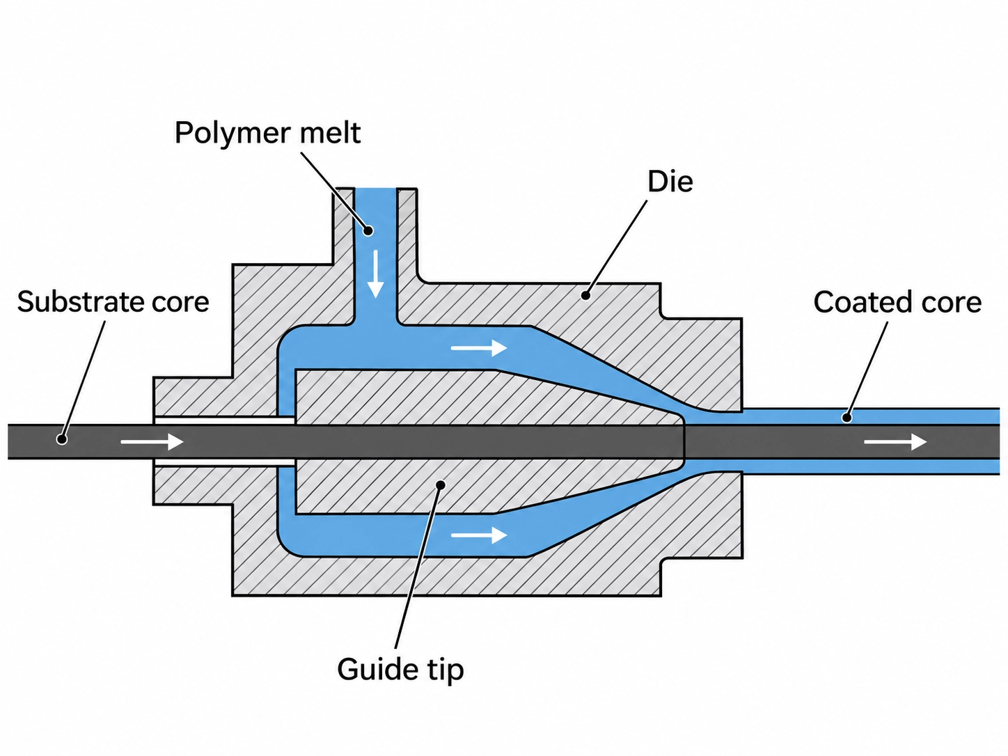
The core travels axially through the head. Polymer from the extruder enters from the side and is redirected toward the coating outlet. The familiar right-angle description refers to the relationship between the incoming melt and the core's travel; it does not mean a rigid core bends through a corner inside the head. These paths are described in the crosshead definitions published by Tips & Dies.
Inside the head, a flow distributor spreads the polymer around the core path. The tip, also called a guider, guides the core, while the outer die shapes the outside of the emerging polymer. These are functional descriptions: the internal arrangement depends on the particular head and product. (Tips & Dies)
Cooling, pulling and checking the coating
The head operates as part of a line. In a flexible wire application, that can include payoff, cooling, a capstan or haul-off, inspection and take-up. Davis-Standard's wire-and-cable page, dated April 26, 2018, lists cooling, pulling equipment, diameter measurement and electrical inspection for an aerospace-wire system. Its configuration illustrates the coordinated system; its listed dimensions and speeds should not be treated as general crosshead coating limits. (Davis-Standard)
When discussing a proposed line, ask how the substrate will be supported and how the finished part will be collected. A reel-based example does not establish suitability for a rigid core. Also ask where inspection occurs and which characteristics it measures. A diameter reading and an interface test answer different questions.
A Coating Is Not Automatically a Bond
Pressure tooling and tubing tooling
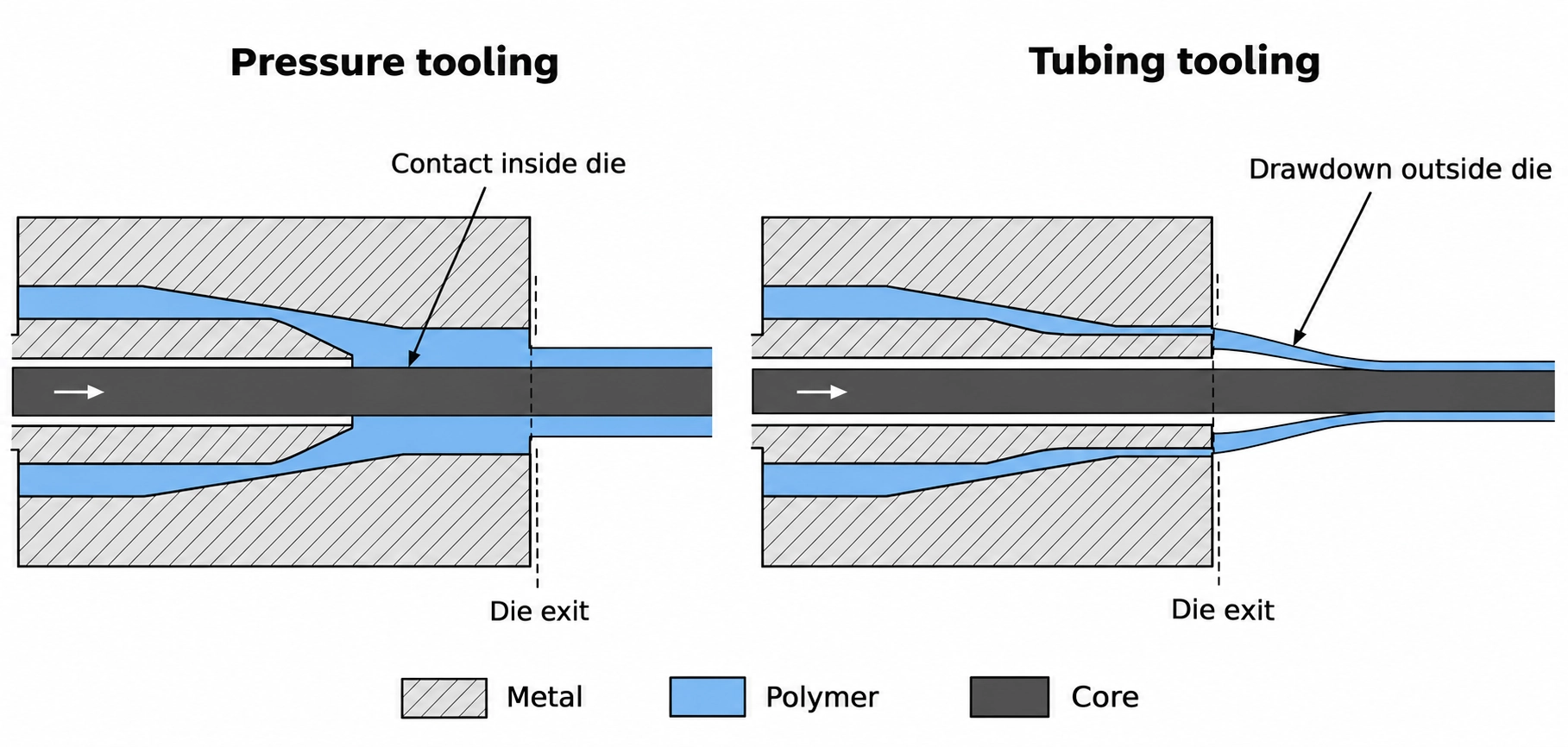
Pressure tooling and tubing tooling differ in where the polymer meets the core. In a typical pressure arrangement, contact occurs inside the die under pressure. In a typical tubing arrangement, polymer emerges as a tube and draws down onto the core outside the die. These descriptions explain the forming mechanism, without establishing the finished adhesion level. (SPiDER EXTRUSION)
Pressure tooling: polymer contacts the substrate inside the die under pressure.
Tubing tooling: polymer emerges as a tube and draws down onto the substrate outside the die.
Tubing tooling does not imply a permanent air gap in the finished product. Nor should pressure tooling be specified as a substitute for demonstrating the required interface behavior. Tooling choice is part of the processing solution, while bond or stripping requirements belong in the product specification.
Guill's 2024 automotive tooling catalog lists pressure, tubing and coextrusion configurations. This confirms that these are established configuration choices; it does not establish that an existing head can accept every configuration without modification. (Guill Tool & Engineering)
Bonded, retained or removable layers
Start by stating what the interface must do. A layer intended to stay attached through service and a jacket intended to strip during termination have different acceptance goals. The following questions are a proposed project-review framework, not universal test requirements.
Mechanical retention may rely on surrounding geometry or physical encapsulation rather than adhesion alone. It does not by itself establish resistance to sliding along the core. Define acceptable relative movement separately from bond strength.
| Intended result | Question to resolve before sample approval |
|---|---|
| Bonded coating | How will attachment be tested, and after which exposure or conditioning? |
| Mechanically retained layer | What movement relative to the core is acceptable during handling and service? |
| Removable jacket | How should it strip, and what damage to the core or underlying layer is unacceptable? |
Avoid an instruction such as "maximum adhesion" if later assembly requires removal. Specify the operation, the acceptable result and the conditions under which it must work. That gives a supplier a clearer target than the word "bonded" alone.
How Crosshead Coating Relates to Coextrusion
Crosshead coating and coextrusion describe different aspects of manufacture. The first concerns coating a pre-existing core through a crosshead; the second concerns combining separately supplied extrusion streams. A multi-layer crosshead can combine both approaches. Tips & Dies defines multi-layer crossheads and coextrusion separately, while Guill lists coextrusion pressure and tubing tooling. (Tips & Dies; Guill Tool & Engineering)
| Description | What it tells you | What still needs clarification |
|---|---|---|
| Crosshead coating | A pre-existing core receives an extruded covering | Layer count and interface requirements |
| Coextrusion | Separate extrusion streams form one construction | Whether a pre-existing core is present |
| Multi-layer crosshead coating | Multiple extruded layers surround a core | Requirements at the core interface and between layers |
Ask for a cross-section identifying the substrate, each layer and each interface. For another example of evaluating a layered structure, see acrylic-capped ABS coextrusion and interface validation. That example explains a different construction and does not establish a supplier's crosshead coating capability.
What Determines Whether a Material Pair Is Feasible
Substrate condition and coating grade
A useful feasibility request identifies the actual substrate and coating grade, rather than only a polymer family. Published application lists are a starting point for discussion; they are insufficient evidence that a particular pair will meet a particular drawing.
Provide the substrate's surface condition as well as its dimensions, including whether any existing lubricant, finish or treatment must be retained, removed or changed. If a bonded interface is required, request evidence for the proposed material pair and surface preparation. If removal is required, explain how the jacket will be stripped and what lies underneath it.
Compatibility also includes the substrate's condition during processing. Review two questions alongside the material and interface requirements:
Thermal exposure: Can the substrate tolerate the proposed thermal exposure without unacceptable changes to its surface, dimensions or function?
Support and handling: Can it remain adequately supported and retain the required geometry and function during feeding, guiding, pulling and cooling?
These are feasibility checks derived from the coating and line mechanisms described above, not a universal material-compatibility rating. Review the actual substrate specification, coating-grade guidance and proposed trial conditions. A coated trial should demonstrate that the core remains acceptable as well as showing the required outer layer; a successful coating appearance alone does not answer these questions.
Geometry, drawdown and process limits
The final coating geometry depends on more than the die opening: drawdown and melt behavior also matter. SPiDER's technical description identifies the tip, die, centering and drawdown as relevant to the resulting wall. This is equipment-supplier guidance, rather than a validated operating window for a new product. (SPiDER EXTRUSION)
The initial review should connect each project detail to a feasibility question:
| Project detail | Feasibility question |
|---|---|
| Core geometry and incoming variation | What dimensional variation must the coating process accommodate? |
| Coating grade and interface objective | What trial will demonstrate the required attachment or release? |
| Coverage and final cross-section | Where are local thickness, fit or exposed regions critical? |
| Service conditions | Which exposures must the coated assembly withstand? |
These are screening questions, not a processing recipe. Temperatures, output, line speed and drawdown settings should come from the selected material guidance and a qualified trial for the actual construction. A setting copied from another polymer or part does not establish feasibility for this one.
What to Check on a Coated Sample
Coverage, minimum wall and centering
An acceptable outside diameter does not prove adequate coating thickness everywhere. A core can sit off-center inside an apparently correct outer envelope. For a circular construction, subtracting core diameter from finished diameter and halving the result gives a nominal concentric wall; it does not establish the thinnest local wall of an eccentric sample.
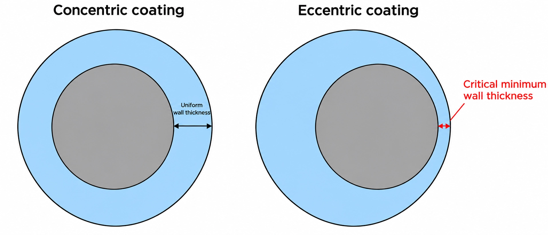
The inspection plan should define section preparation and measurement, sample locations and the dimensions that control acceptance. For circular samples, agree on circumferential measurement positions as well as section locations before comparing local wall thickness across samples. For background on these distinctions, see tube dimensions, wall variation and inspection methods. Adapt those measurement concepts to the actual coated core and drawing.
Interface behavior and application requirements
Keep appearance, dimensions, interface behavior and functional performance separate in the approval record. The table below proposes a way to organize that record; the drawing and applicable product requirements must supply the methods and acceptance limits.
| Requirement | Check to agree | Record to retain |
|---|---|---|
| Coverage and appearance | Inspect defined areas for exposed core and unacceptable surface defects | Sample identity, inspection conditions and photographs |
| Local wall and centering | Measure agreed cross-sections using a suitable method | Section locations, measurements and drawing revision |
| Attachment or removability | Perform the agreed bond, retention or stripping evaluation | Method, conditioning and observed result |
| Performance in use | Select tests relevant to the application, such as electrical integrity or environmental exposure | Applicable specification, conditions and results |
A visually smooth sample cannot replace functional evidence. Equally, a successful initial interface test answers only the conditions tested. If service exposure is relevant, decide whether the acceptance evaluation must be repeated after that exposure. Avoid treating a coating-material datasheet as certification of the finished assembly.
Information to Prepare Before a Feasibility Review
Prepare a compact project package that lets the supplier identify unresolved questions:
Project package checklist
A drawing or cross-section identifying the substrate, layers and coverage areas.
Substrate material, dimensions, incoming variation and surface condition; a representative sample where available.
Proposed coating grade, or the functions and constraints that material selection must satisfy.
The intended interface behavior, including any stripping or assembly operation.
Service conditions and the dimensional and functional requirements that determine acceptance.
Trial quantity, expected production quantity and the form in which the core will be supplied.
Mark requirements that are still provisional. This helps distinguish a request to explore a construction from a request to manufacture against an approved specification.
To ask Dachang to review your coating project requirements, email the project package to ken@euson.cn, as listed on the contact page. Start with the drawing and intended interface behavior, and ask whether Dachang can support the construction and what information or samples would be needed for a feasibility review. You can also browse Dachang's current extrusion product range to understand the products publicly presented.