

When square plastic tubing has to fit an existing connector, start with the surfaces that actually touch. For a push-in end cap, compare the insert with the tube opening, including the corners. For a cap that slips over the tube, compare the sleeve opening with the tube's outside shape. Then cut and dry-fit both ends and measure the finished assembly. A part that starts easily can still bind before its shoulder seats, and a cap that seats can still rock beyond the permitted limit.
This guide is for product and manufacturing engineers checking non-load-bearing trim, covers, and end-cap assemblies on retail display fixtures or storage equipment. It covers unpressurized assemblies and uses the actual connector drawing and parts as the basis for acceptance.
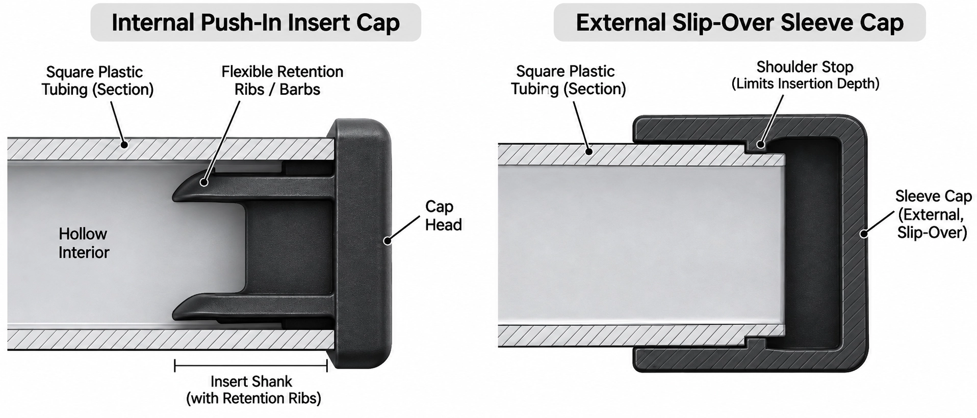
Identify the Joint Before Measuring the Tube
Internal Insert or External Sleeve?
| Joint | Tube surfaces to check | Mating part features to check |
|---|---|---|
| Internal insert or push-in cap | Inside width in both directions, internal corner radii, straight engagement length, wall thickness where retention features bear | Insert width in both directions, corner shape, rib or barb envelope, shoulder, specified insertion depth |
| External sleeve or slip-over cap | Outside width in both directions, external corner radii, usable engagement length | Sleeve opening in both directions, internal corners, usable depth, stop or seating face |
Mark the insertion direction and the datum used to tell when the joint is seated. For a shouldered cap, the drawing may specify a face-to-shoulder gap. For a recessed plug, use the specified position relative to the tube end. Record the part number and revision of the connector itself. Check the catalog limits for the exact connector part number. For example, the Essentra 550374 CAD catalog entry lists both compatible tube size and maximum wall thickness for a push-fit connector. Those specifications apply only to that connector and its listed tube size.
Check Width, Wall Thickness, and Corner Clearance
Compare the Tube and Connector at Their Fit Limits
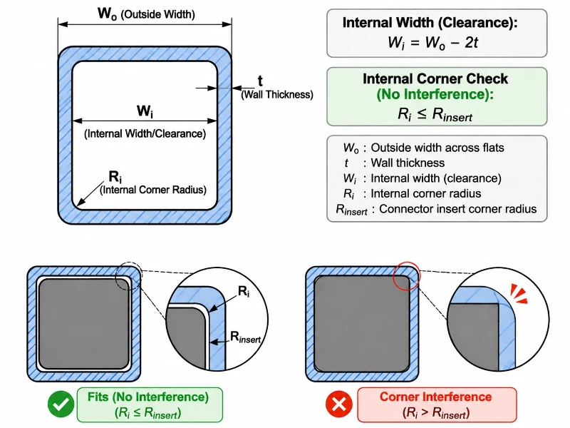
For a clearance-fit insert, compare the smallest permitted tube opening with the largest permitted insert. For a clearance-fit sleeve, compare the smallest sleeve opening with the largest permitted tube exterior. Check both axes. Then compare the other limits to see how much play the loosest combination could allow. If the connector uses compressible ribs or intentional interference, use the drawing's allowable engagement, insertion force, and retention criteria where specified. Confirm them on actual parts.
Widths across the flats are a first check. An insert can clear both flats and still touch the tube's internal corners. Compare the two end profiles at the same orientation and check features that change along the insertion path, such as ribs and tapers. For thin walls, use a measurement method that avoids squeezing the section. Check the cut ends and the required engagement length with the agreed gauge or a reference part identified in the inspection plan. Lakeland's extrusion design guide lists wall thickness, hollow sections, and radii among its design considerations. (Lakeland Plastics)
For parallel flats, estimate inside width along each axis by subtracting the thickness of both opposing walls from the outside width. Use the smallest allowed outside width and the largest allowed thickness for each opposing wall to estimate a worst-case opening across those flats. That estimate leaves out corner clearance and profile distortion. If the catalog gives only nominal dimensions, ask for a controlled inside profile or a functional gauge requirement before approving the insert. If a different supplier will make the same nominal section, specify the measurement locations, methods, and limits in the release drawing. Dachang's custom tube drawing and inspection requirements explain how to put those checks into a supplier specification.
Cut to Length and Dry-Fit the Assembly
Check the Cut End and Mark the Seating Depth
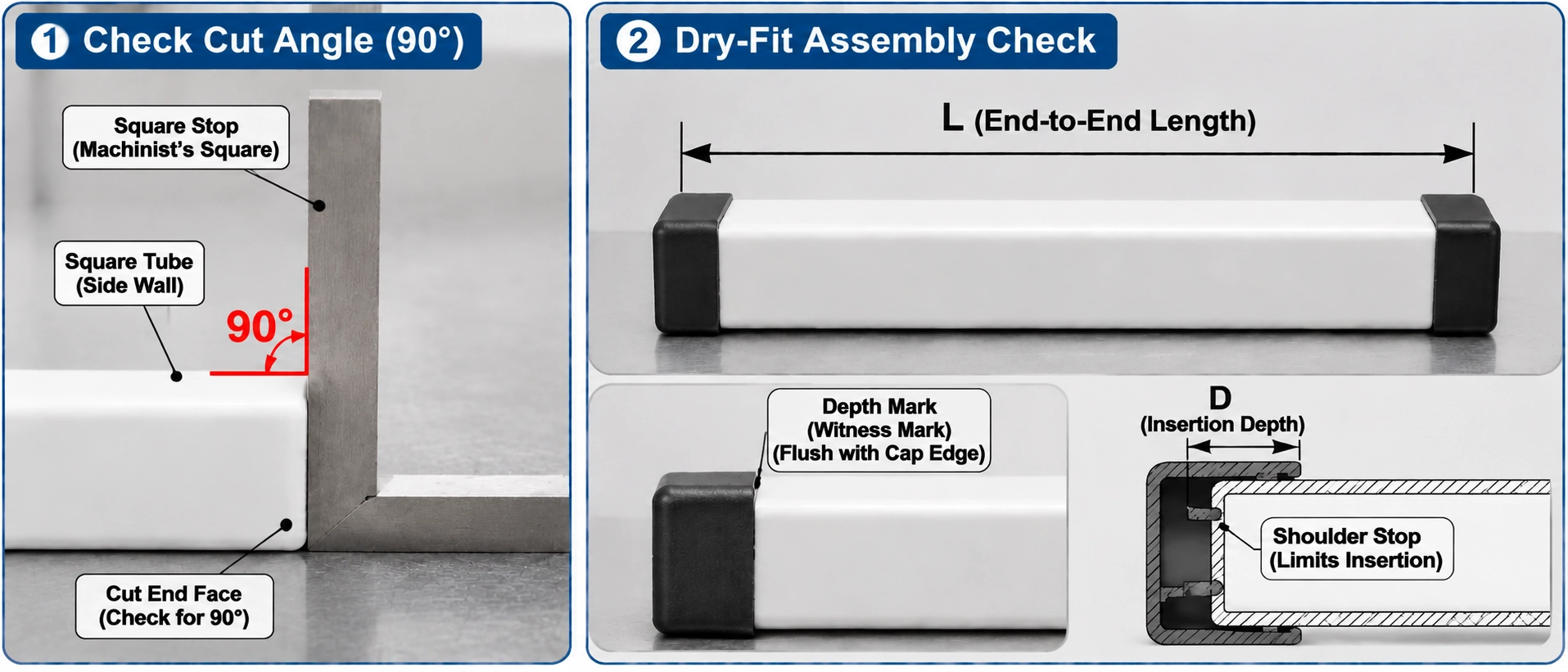
- Work back from the assembled dimension. If the outside faces of two seated caps define the finished length, subtract the amount each cap projects beyond its tube end. Measure each projection from the tube end with the cap in its specified seated position, including any shoulder gap. For a different joint, use the drawing datums and the effective seated position at each end.
- Cut a trial piece using the work instruction for the tube material. Support the section so the fixture holds the part without crushing it. Check length from the drawing datum. To check end squareness, compare the cut face against a square stop in both directions and check any gap against the drawing limit. Inspect for cracks, chips, burrs, and distortion. Use the specified deburring method and preserve the seating face and retention edges.
- Verify seating at both ends. Mark the specified insertion depth or use the fixture stop. Try the production-representative connector using the assembly work instruction. Check for binding, deformation, and visible damage such as cracks at the tube opening or corners. Verify shoulder gap or recess, end-to-end length, and alignment in the assembly fixture.
- Complete the joint as specified in the assembly work instruction. If the joint requires a separate retainer, fastener, or bonding operation, recheck seating and final geometry after that operation.
BWF's November 2024 processing guide for PMMA and PC profiles separates length and straightness checks, shows straightness checks in both directions, and uses a stop and gap measurement to inspect saw-cut angle. It also checks precision-cut ends for cracks, chips, and burrs. Use the inspection methods as a reference and take your acceptance limits and process settings from the project drawing and material work instructions. (BWF Profiles, sections 2.2, 4.3, and 4.7)
Record the First-Article Fit Check
Record tube and connector part numbers, drawing revisions, production lots, the assembly fixture, the measurement method, and the temperature at which the parts were checked. For long trim sections or assemblies with both ends constrained, verify the fit at the specified service conditions using the project materials and restraints. The tube and connector can change dimensions by different amounts as temperature changes, which can affect clearance or seating. Agree on the inspection checks before trying the parts, then record the actual findings.
| First-article check | What to record | Acceptance basis |
|---|---|---|
| Tube and connector geometry | Measurements at defined locations or functional gauge result, including the corners and engagement zone | Released drawing limits or agreed functional gauge |
| Cut length and end finish | Measured cut length, end squareness, and condition of both cut faces | Drawing and work instruction for edge finish |
| Seating at each end | Insertion depth, shoulder gap or recess, and any surface damage | Specified seated position and visual limits |
| Alignment and finished length | Assembly fixture result and finished length between drawing datums | Assembly drawing limits |
| Fit in use | Play or retention result where required, with test location, method, conditions, and any change after conditioning | Agreed functional limits and verification method |
| Disposition | Pass, hold, or recheck, with affected lots and reviewer sign-off | First-article plan and separate lot acceptance rules |
Diagnose Tight, Loose, or Uneven Joints
- Stops at the opening. Check orientation, burrs, and corner contact before changing the width specification.
- Starts, then binds. Record where it stops. Check for taper, ribs that engage deeper in the joint, and local tube distortion along the engagement length.
- Seats but rocks or pulls out too easily. Compare the actual mating dimensions against the loose-fit limits and check whether the retention features engage as designed.
- One end sits proud or the assembly is misaligned. Compare end squareness and shoulder position at each end. Check bow and twist with the tube unrestrained, then verify alignment in the assembly fixture.
When the inspection plan allows it, try the suspect tube with a reference connector and the suspect connector with a reference tube identified in the inspection plan. Keep orientation and test conditions consistent and record each combination. Hold affected parts if the specified criteria are missed. The first-article result documents the checked sample. Later lots follow the agreed sampling and acceptance rules.
Compare Your Drawing With Dachang's uPVC Square Tube
The Dachang uPVC square tube has a listed nominal section of 124 × 124 mm and a nominal wall of 2 mm. The product page lists 800, 1,200, and 2,110 mm lengths and a custom length option. Use these catalog dimensions for initial screening. The specification table gives no dimensional tolerances, inside width, corner radii, or mating connector specification. Use the tube and connector drawings and a representative assembly to verify the fit for your project.

| Fit question | What the product page supplies | What your project needs to confirm |
|---|---|---|
| Will an external sleeve clear the tube? | Nominal 124 × 124 mm section | Maximum outside profile across both axes, external corner shape, sleeve opening limits, and seating depth |
| Will an insert seat and stay in place? | uPVC and nominal 2 mm wall | Minimum inside profile across both axes, internal corner shape, insert limits, and measured retention where required |
| Will the assembly meet its finished length? | Listed length examples and a custom length option | Tube cut length, tolerance, end squareness, and assembled length with both connectors seated |
If the existing product is close to your required outer section, compare toleranced drawings before committing to the connector or a bulk order. If your existing connector requires a different wall, opening, or corner geometry, start with that mating part when discussing a custom section.
What to Include in a Custom Square Tube Inquiry
For custom plastic tube extrusion, send Dachang the current tube and mating-part drawings. Include the information that governs the fit and the quote.
- Cross-section and material. Give the specified material or grade, wall thickness limits, and minimum and maximum widths along both axes of the mating surfaces. Include the corner geometry and identify the part and drawing revisions.
- Assembly and cut length. Specify the seating depth or shoulder position, the tube cut length and tolerance, the finished assembly dimension, and the expected temperature range in use.
- Production and samples. Include the expected order quantity. For a replacement tube, identify the approved reference sample and describe where the substitute binds, rocks, or fails to seat.
Request a Square Tube Quote for the listed section or a custom profile. Send your tube and connector drawings to the email address on the inquiry page and ask Dachang to confirm which dimensions it would use to quote for your connector fit.